1600i Digifant ECU pinouts
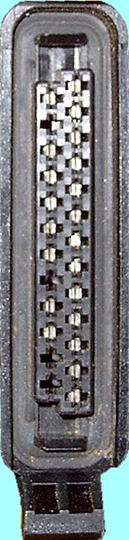
Connector Layout (ECU End - outer)
Connector Layout (Cable End - outer)
ECU Cable Harness Plug
| Pin # | Purpose | Wire Colour(s) |
| 1 | Ignition (+12V) | Red/Black |
| 2 | Lamda Sensor | Black |
| 3 | Petrol Pump Relay (red/yellow) and Alarm Module (black/blue) | Red/Yellow |
| 4 | Idle Speed Stabilizer | White |
| 5 | Magnetic Valve for Activated Charcol Cannister | Green/Yellow |
| 6 | Ground connections for the following:- - Hall Sensor - Engine Oil - Temperature Sensor - Air Temperature Sensor - Throttle Potentiometer |
Brown/White |
| 7 | Linked to pin 6 | Brown |
| 8 | Hall Sensor (+) | Red/Black |
| 9 | Air Temperature Sensor (+) | Purple/Black |
| 10 | Engine Oil Temperature Sensor (+) | Brown/Red |
| 11 | Throttle Potentiometer | Yellow/Red |
| 12 | Fuel Injectors Ground Connection | Brown |
| 13 | Ground connections for the following:- Diagnostics Connector T3/2 Ignition Transformer (terminal 31) |
Brown |
| 14 | ECU Relay Positive Supply (via fuse 7) | Black/Yellow |
| 15 | (Not Connected) | |
| 16 | Ground | Brown |
| 17 | Throttle Potentiometer (signal) | Blue |
| 18 | Hall Sensor (signal) | Green/White |
| 19 | Ground | Brown |
| 20 | Diagnostics Connector K-Line T3/1 | Brown/White or Grey |
| 21 | (Not Connected) | |
| 22 | ECU Relay - Ignition Control | Black/White |
| 23 | Ignition Transformer (terminal 1) | Black/White |
| 24 | (Not Connected) | |
| 25 | (Not Connected) |
Connector Layout (ECU End - outer)
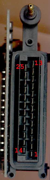
Connector Layout (Cable End - outer)
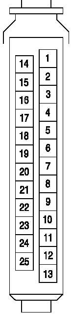
ECU Cable Harness Plug